Unlocking Electronics: Your Guide to Essential Circuit Symbols

Ever looked at a circuit diagram and felt like you were deciphering hieroglyphics? Don't worry, you're not alone. Understanding electronic schematic symbols is like learning the alphabet of electronics. Once you grasp these fundamental representations, you'll unlock the secrets of circuit design and be able to read and interpret electronic blueprints with confidence.
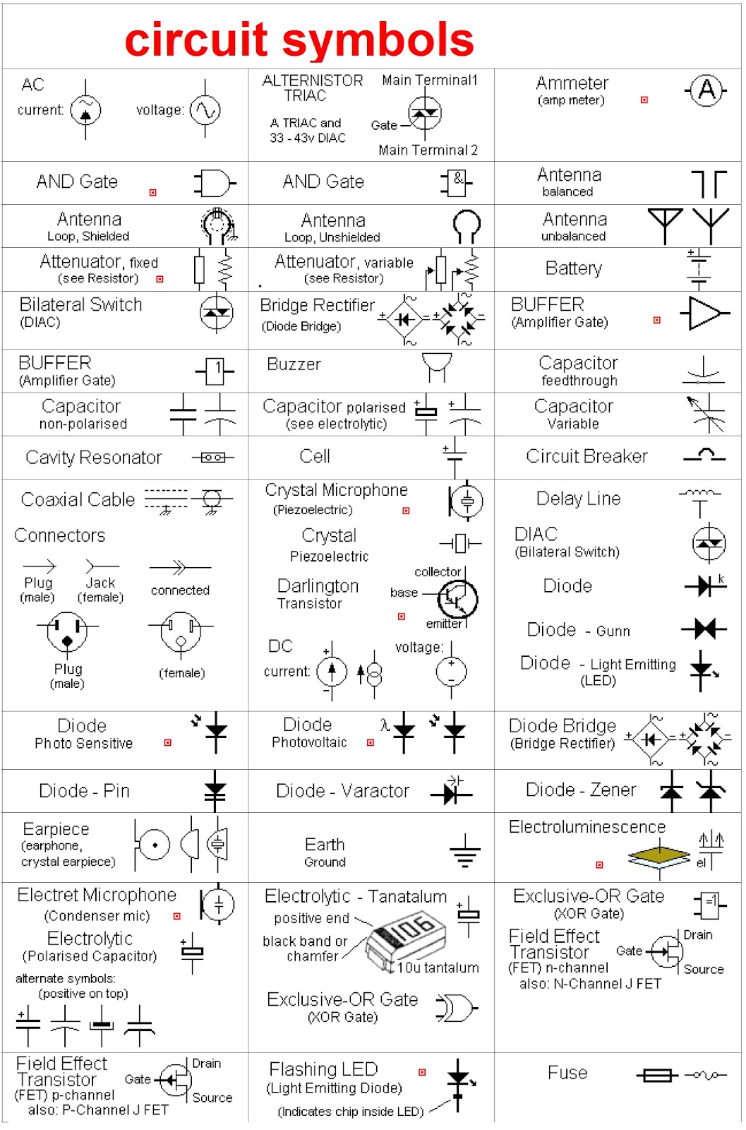
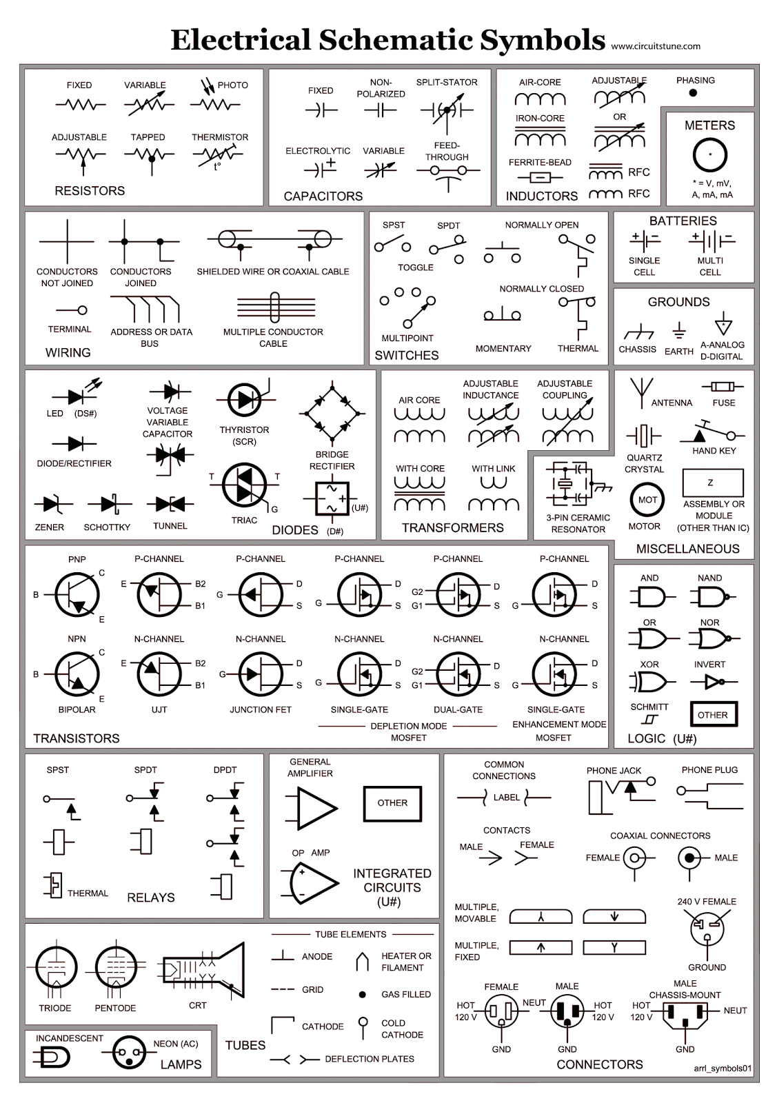
Electronic schematic symbols are standardized visual representations of electronic components used in circuit diagrams. These symbols are the building blocks of any electronic design, enabling engineers and hobbyists to communicate complex circuit designs efficiently. Imagine trying to describe a complex circuit using only words – it would be a confusing mess. Schematic symbols provide a clear, concise, and universally understood language for electronics.
The history of these symbols dates back to the early days of electronics, evolving alongside the technology itself. Initially, symbols were often crude representations of the physical components. However, as electronics became more complex, the need for standardized symbols became crucial. Organizations like the Institute of Electrical and Electronics Engineers (IEEE) and the International Electrotechnical Commission (IEC) played a vital role in establishing and maintaining these standards.
These graphic representations are essential for designing, analyzing, and troubleshooting electronic circuits. They allow engineers to visualize the connections between components and understand the flow of current and signals within the circuit. Without a standardized set of symbols, collaborative design would be nearly impossible, leading to misinterpretations and potentially dangerous circuit malfunctions. One of the main issues related to schematic symbols is ensuring consistent usage and interpretation across different regions and industries. While standardization efforts have greatly reduced ambiguity, variations and outdated symbols can still cause confusion.
Learning to read and understand these visual representations of components is like learning a new language, one that opens doors to a world of electronic innovation. From simple resistors and capacitors to complex integrated circuits, each symbol tells a story about the component's function and its role within the larger circuit.
One of the biggest benefits of using standard electronic schematic symbols is the clear communication they facilitate. Engineers worldwide can understand a circuit diagram regardless of language barriers. For example, a resistor symbol is instantly recognizable whether you're in Japan or Brazil. This universal language fosters collaboration and speeds up the design process.
Another advantage is the simplification of complex designs. By using abstract symbols, engineers can represent intricate circuits in a concise and easy-to-understand manner. Imagine trying to draw a realistic picture of every component in a smartphone circuit – it would be impractical. Schematic symbols allow for a manageable representation of even the most complex electronic systems.
Finally, these standardized representations are crucial for troubleshooting and circuit analysis. By tracing the connections and understanding the function of each component represented by its symbol, technicians can quickly identify faults and repair malfunctioning electronics. This saves valuable time and resources.
Advantages and Disadvantages of Standardized Electronic Schematic Symbols
| Advantages | Disadvantages |
|---|---|
| Clear communication and universal understanding | Requires learning and memorization of symbols |
| Simplification of complex designs | Potential for misinterpretation if non-standard symbols are used |
| Efficient troubleshooting and circuit analysis | Can become cluttered in highly complex circuits |
Best practices for using schematic symbols include adhering to established standards (IEEE/IEC), ensuring consistent symbol usage throughout a design, clearly labeling all components, and maintaining a neat and organized diagram. Using software tools specifically designed for schematic capture can also greatly improve efficiency and accuracy.
Real-world examples of schematic symbols in action include the design of circuits for everything from simple LED flashlights to complex computer systems. These symbols are the foundation of electronic design, enabling the creation of the countless electronic devices we rely on every day.
Frequently asked questions about schematic symbols often revolve around identifying specific symbols, understanding their meaning, and finding resources for learning more. Many online resources, textbooks, and software tools provide comprehensive libraries of symbols and tutorials on their usage.
Tips and tricks for working with schematic symbols include using online symbol libraries, practicing drawing common symbols, and utilizing software tools with built-in symbol checking features. These tools can help ensure accuracy and consistency in your designs.
In conclusion, understanding basic electronic schematic symbols is fundamental to anyone working with electronics. These symbols provide a common language for designers, technicians, and hobbyists, enabling effective communication and efficient circuit design. From the simplest resistor to the most complex integrated circuit, these graphical representations are the building blocks of electronic innovation. Mastering these symbols empowers you to unlock the secrets of electronics, enabling you to design, analyze, and troubleshoot circuits with confidence. Explore the resources available, practice regularly, and embrace the power of this essential electronic language. Your journey into the fascinating world of electronics begins with understanding these fundamental symbols.
Nba in season tournament bracket predictions and analysis
Connelly big easy wakesurf board ride the endless wave
Remembering brown and pennington exploring obituary notices

.jpg)


