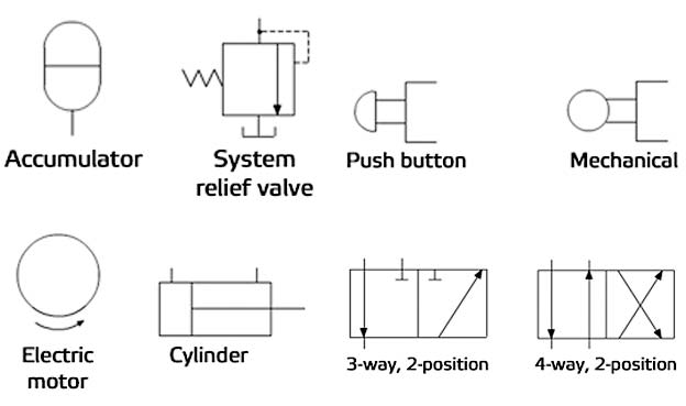
Understanding Pump Symbols in Hydraulic Circuits
Hydraulic circuits are the lifeblood of countless machines, from construction equipment and aircraft to industrial robots and agricultural machinery. These intricate systems rely on the precise control and movement of fluids under pressure to perform work. Understanding the symbolic language used to represent these circuits is essential for anyone involved in their design, maintenance, or operation. At the heart of these schematic representations lies the pump symbol, a crucial element that depicts the driving force behind the entire hydraulic system.
The pump symbol in a hydraulic circuit diagram signifies the power source responsible for generating the flow of hydraulic fluid. This flow, carefully controlled through valves and other components, enables the system to perform its intended function. Without the pump, the hydraulic circuit would be inert, unable to transmit power or perform any work. Therefore, correctly interpreting the pump symbol is fundamental to understanding the overall system operation.
While seemingly simple, the pump symbol conveys critical information about the type of pump being used. Variations in the symbol can indicate whether the pump is fixed displacement or variable displacement, unidirectional or bidirectional, and can even offer clues about its control mechanisms. This concise visual representation allows engineers and technicians to quickly grasp the essential characteristics of the pump and its role within the larger hydraulic system.
The standardized representation of pump symbols emerged alongside the development of hydraulic technology itself. As hydraulic systems became more complex, the need for a clear and universally understood method of depicting their components grew. This led to the adoption of standardized symbols, including those for pumps, valves, actuators, and other key elements. These symbols, often governed by industry standards like ISO 1219-1, ensure consistency and clarity in hydraulic circuit diagrams across different industries and geographical locations.
The importance of accurate and standardized pump symbols in hydraulic circuits cannot be overstated. These symbols facilitate effective communication among engineers, technicians, and operators, minimizing the risk of misinterpretations that can lead to costly errors or safety hazards. A standardized symbol ensures that everyone involved in the hydraulic system understands the function and characteristics of the pump, enabling efficient troubleshooting, maintenance, and system optimization.
A simple example of a pump symbol is a circle with an arrow pointing outwards, indicating the direction of fluid flow. A triangle added to the symbol can indicate a variable displacement pump. A bidirectional pump might be shown with two opposing arrows.
Benefits of standardized pump symbols include improved communication, easier troubleshooting, and simplified design and modification of hydraulic circuits. For example, a technician can quickly identify the type of pump used in a system by looking at the symbol on the diagram, saving valuable time during maintenance.
An action plan for using pump symbols effectively involves familiarizing oneself with the relevant ISO standards, using software tools with built-in symbol libraries, and consistently applying these symbols in all hydraulic circuit diagrams.
Advantages and Disadvantages of Standardized Pump Symbols
| Advantages | Disadvantages |
|---|---|
| Clear communication | Requires learning the standard symbols |
| Efficient troubleshooting | Can be complex for highly specialized pumps |
| Simplified design |
Best practices include adhering to ISO standards, ensuring consistency in symbol usage, and providing clear labels and annotations on diagrams.
Real-world examples of pump symbols can be found in hydraulic circuit diagrams for excavators, airplane control systems, and industrial presses.
Challenges in using pump symbols can include variations in regional standards or software limitations. Solutions involve adhering to the most widely accepted standards and using compatible software tools.
Frequently asked questions about pump symbols often relate to their meaning, variations, and standardization.
Tips for using pump symbols effectively include using clear and concise labels and maintaining consistency in their application.
In conclusion, the pump symbol in a hydraulic circuit diagram is a critical element for understanding and interpreting how a hydraulic system functions. Its standardized representation ensures clarity and minimizes misinterpretations, allowing engineers, technicians, and operators to communicate effectively. By adhering to established standards and best practices, professionals can leverage the power of these symbols to design, maintain, and troubleshoot hydraulic systems efficiently and safely. Understanding and correctly using pump symbols is essential for anyone working with hydraulic systems, ensuring proper functionality, maintenance, and safety. Investing time in learning these symbols and their variations will significantly contribute to a deeper understanding of hydraulic circuits and their operation.
My mom my first friend my forever friend
Elevate your outdoor sanctuary the magic of porch ceiling blue
Conestoga college international admissions guide


