Decoding Hydraulic Schematics The Language of Fluid Power

Ever looked at a hydraulic schematic and felt overwhelmed by the cryptic symbols? You're not alone. Hydraulic diagrams, filled with their unique language of shapes and lines, can seem daunting at first. But deciphering these visual cues is essential for anyone working with hydraulic systems, from design and maintenance to troubleshooting and repair. This article dives deep into the world of hydraulic signs and symbols, providing a roadmap to understanding their importance and practical application.
Imagine trying to assemble a complex piece of furniture without instructions. Hydraulic schematics serve as the instruction manual for fluid power systems. These diagrams communicate vital information about the components, connections, and flow of hydraulic fluid within a system. Without a firm grasp of hydraulic symbology, navigating these schematics becomes an impossible task, increasing the risk of misinterpretations and potentially hazardous situations.
The genesis of standardized hydraulic symbols arose from the need for a universal language in the fluid power industry. As hydraulic systems became more complex, the limitations of written descriptions became apparent. Standardized symbols provided a concise and unambiguous way to represent various components, regardless of language barriers or technical jargon. This standardization not only facilitated communication but also enhanced safety and efficiency in the design, operation, and maintenance of hydraulic systems.
One of the core issues surrounding hydraulic signs and symbols is the importance of adhering to established standards. While variations might exist, sticking to recognized standards like ISO 1219-1 ensures clear communication and prevents confusion. These standards dictate specific shapes and symbols for different components, ensuring that a pump symbol in one schematic represents the same component in another, regardless of the manufacturer or country of origin. Consistency is key to accurately interpreting and utilizing hydraulic diagrams.
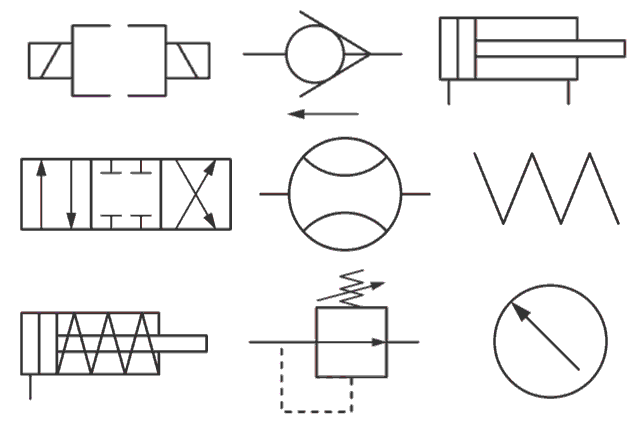
Understanding the basic building blocks of hydraulic symbology is the first step towards fluency in this visual language. For example, a circle typically represents a pump, while a square denotes a valve. Lines connecting these shapes depict the flow path of hydraulic fluid. Variations within these basic shapes, such as arrows or different fill patterns, further refine the component's function. For instance, a triangle within a square signifies a check valve, indicating unidirectional flow. Learning these fundamental elements is like learning the alphabet of hydraulic diagrams.
Three key benefits of using standardized hydraulic signs and symbols are improved communication, enhanced safety, and streamlined troubleshooting. Clear communication ensures that everyone involved in the design, operation, and maintenance of a hydraulic system understands its functionality. Enhanced safety stems from the unambiguous representation of components and their connections, minimizing the risk of errors during operation or maintenance. Streamlined troubleshooting becomes possible because standardized symbols allow technicians to quickly identify faulty components and understand the system's behavior.
Advantages and Disadvantages of Standardized Hydraulic Symbols
| Advantages | Disadvantages |
|---|---|
| Clear Communication | Requires Initial Learning |
| Enhanced Safety | Potential for Misinterpretation if Standards Aren't Followed |
| Streamlined Troubleshooting | Can be Complex for Highly Detailed Systems |
Best Practices for Implementing Hydraulic Symbols: 1. Adhere to ISO Standards. 2. Use clear and concise labels. 3. Maintain consistency throughout the schematic. 4. Provide a legend or key explaining all symbols. 5. Regularly review and update schematics as needed.
Frequently Asked Questions: 1. What is the symbol for a hydraulic pump? 2. How is a directional control valve represented? 3. What does a dashed line signify in a hydraulic schematic? 4. Where can I find a comprehensive list of hydraulic symbols? 5. What are the different types of hydraulic actuators and their symbols? 6. How are pilot lines represented in a schematic? 7. What is the significance of different line thicknesses in a hydraulic diagram? 8. How can I learn more about interpreting hydraulic schematics?
In conclusion, the language of hydraulic signs and symbols is fundamental to the safe and efficient operation of hydraulic systems. From design and maintenance to troubleshooting and repair, understanding these visual cues is crucial for anyone working with fluid power. By mastering this specialized language, we empower ourselves to communicate effectively, prevent accidents, and optimize the performance of hydraulic equipment. Embrace the challenge of learning hydraulic symbology, and you'll unlock a deeper understanding of the intricate world of fluid power. This knowledge will not only enhance your professional skills but also contribute to a safer and more productive work environment. So, dive in, explore the resources available, and become fluent in the language of hydraulics.
Conquering the road mastering your toyota highlander wheel torque
Water birth adventures exploring childbirth at sea
Finding your true north decoding the feng shui house direction dilemma


