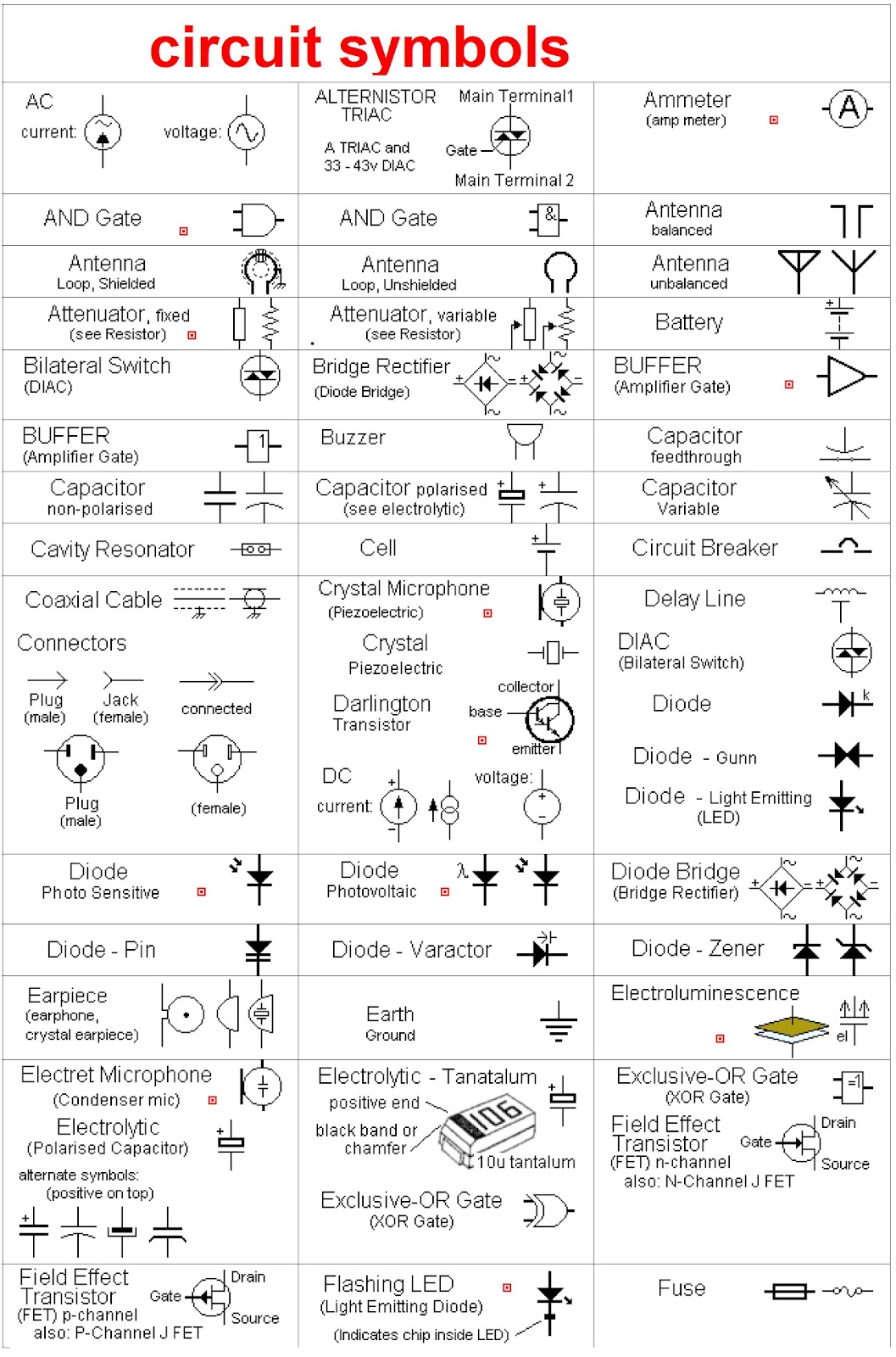
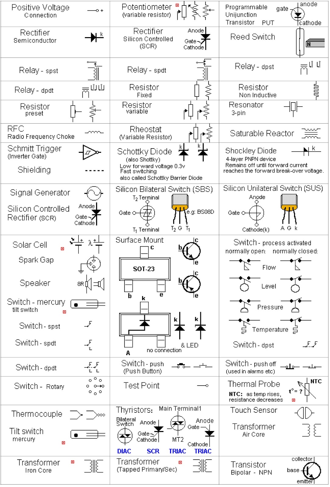
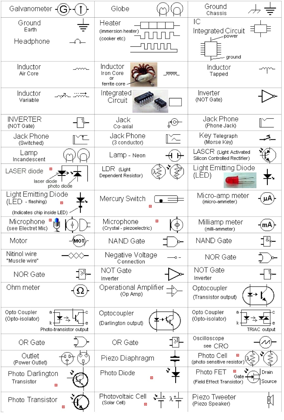
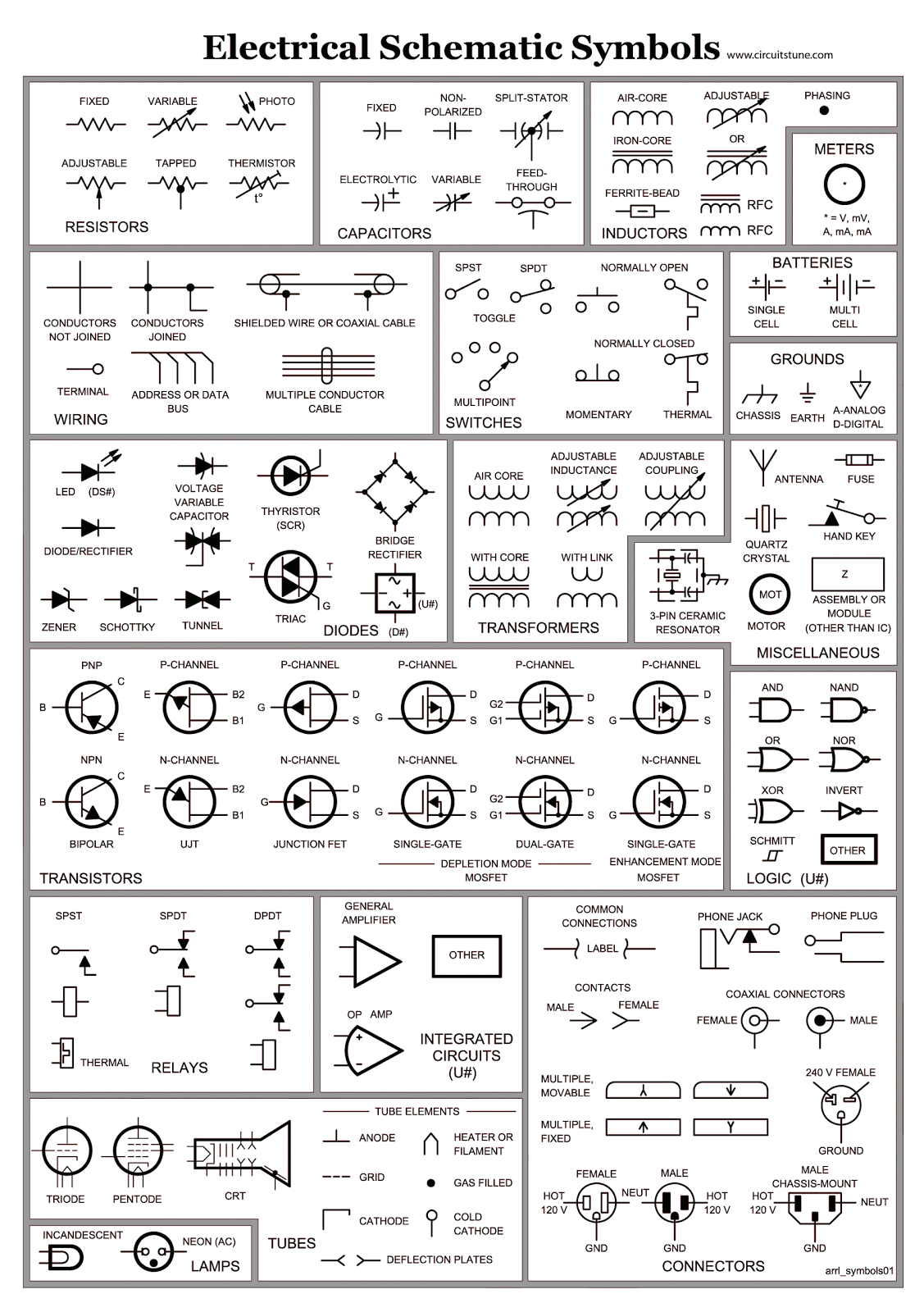
Decoding Circuit Secrets Electronic Schematic Symbols

Ever stared at a circuit board and felt like you were looking at an alien language? Those squiggles, lines, and circles aren't random doodles; they're electronic schematic diagram symbols, the universal language of electronics. Understanding these symbols is key to deciphering circuit diagrams and building or repairing electronic devices. This guide will take you on a journey through the fascinating world of electronic schematic symbols, from their historical roots to practical applications.
Imagine trying to assemble furniture without instructions. That's what working with electronics is like without understanding schematic symbols. These symbols represent electronic components like resistors, capacitors, transistors, and integrated circuits. They depict how these components connect, forming a visual representation of the circuit's function. Without these visual aids, electronic design and troubleshooting would be incredibly challenging.
The history of schematic symbols is intertwined with the development of electronics itself. Early schematics were often hand-drawn, and standardization wasn't widespread. As electronics evolved, so did the need for a common language. Organizations like the Institute of Electrical and Electronics Engineers (IEEE) and the International Electrotechnical Commission (IEC) played crucial roles in developing and standardizing the symbols we use today. This standardization enables engineers worldwide to collaborate and understand each other's work seamlessly.
The primary concern with electronic schematic symbols is understanding their meaning and application. Misinterpreting a symbol can lead to faulty circuit designs, malfunctioning devices, and even safety hazards. It's essential to learn the correct representation of each component and how they interact within a circuit. This knowledge is fundamental to both designing new circuits and troubleshooting existing ones. A solid grasp of these symbols is vital for anyone working with electronics.
A resistor, represented by a zig-zag line, controls current flow. A capacitor, symbolized by two parallel lines, stores electrical energy. A diode, depicted by a triangle with a line, allows current to flow in one direction but blocks it in the other. These are just a few basic examples. Learning to recognize and understand these symbols opens up a world of electronic possibilities.
One benefit of standardized electronic schematic symbols is clear communication. Imagine trying to explain a complex circuit using only words – it would be a nightmare. Schematic diagrams provide a concise and universally understood visual representation. Secondly, they simplify troubleshooting. By visually tracing the connections and components in a schematic, you can quickly identify potential problems. Thirdly, schematic diagrams enable efficient design. They provide a blueprint for building circuits, allowing engineers to plan and optimize before physically assembling components.
Advantages and Disadvantages of Standardized Electronic Schematic Symbols
| Advantages | Disadvantages |
|---|---|
| Clear and concise communication | Requires learning and memorization |
| Simplified troubleshooting | Can be complex for large circuits |
| Efficient circuit design | Different standards may exist (though less common now) |
Best Practices:
1. Use the correct and standardized symbols for each component.
2. Keep the schematic diagram clean and organized.
3. Use labels and annotations to clarify complex sections.
4. Ensure consistent orientation and flow in the diagram.
5. Regularly review and update your knowledge of symbols.
Real-World Examples: Schematics are used in everything from smartphones and laptops to cars and airplanes. They're essential for designing and repairing complex electronic systems.
Challenges and Solutions: One common challenge is keeping up with new symbols as technology evolves. The solution is to consult updated resources and standards.
FAQs:
1. What is a schematic diagram? - A visual representation of an electronic circuit.
2. Where can I learn more about schematic symbols? - Online resources, textbooks, and software tools.
3. Are there different types of schematic diagrams? - Yes, there are different levels of detail, from block diagrams to detailed circuit schematics.
4. Why is standardization important? - For clear communication and collaboration.
5. How can I improve my schematic reading skills? - Practice and study.
6. What software can I use to create schematics? - There are various free and commercial schematic capture software available.
7. What's the difference between a schematic and a PCB layout? - A schematic shows the logical connections, while a PCB layout shows the physical arrangement of components on a board.
8. How can I find the meaning of an unfamiliar symbol? - Consult datasheets, component libraries, or online resources.
Tips and Tricks: Utilize online component libraries and schematic software to learn and practice.
In conclusion, electronic schematic diagram symbols are the fundamental building blocks of electronic design and understanding. From their historical development to their practical applications in every electronic device we use, these symbols play a crucial role. Mastering these symbols unlocks the ability to design, build, and troubleshoot circuits, opening doors to a world of electronic innovation. The benefits of using standardized symbols, including clear communication and efficient troubleshooting, are indispensable. By consistently learning and applying best practices, you can navigate the intricate world of electronics with confidence and create innovative electronic solutions. Take advantage of the numerous resources available, including online tutorials, textbooks, and software tools, to expand your knowledge and become proficient in interpreting and using electronic schematic diagram symbols. Start exploring, practice regularly, and you'll discover that the seemingly cryptic world of electronics becomes clearer and more accessible.
Navigating the sister best friend bond
The art of automotive upholstery cleaning cloth car seats
Decoding the 5x120 bolt pattern which rides rock this setup


.jpg)


