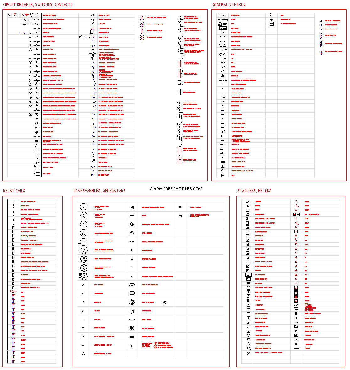
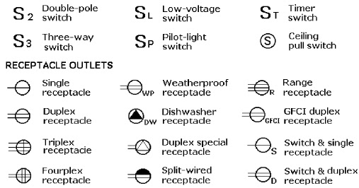
AutoCAD Electrical Symbols: Your Wiring Diagram Wingman

So, you're staring at a blank AutoCAD screen, ready to conquer the world of electrical design. But wait. Where are all those little squiggles and circles that make an electrical drawing, well, electrical? You're talking about electrical symbols in AutoCAD, my friend, and they're more important than a triple-shot latte on a Monday morning.
Imagine trying to read a map without any symbols. A chaotic mess, right? The same goes for electrical drawings. AutoCAD electrical symbols are the visual language of circuits, providing a standardized way to represent components like resistors, capacitors, switches, and more. Without them, you'd be left with a jumble of lines that would make even the most seasoned electrician scratch their head.
These symbols weren't conjured up overnight. They've evolved over time, shaped by industry standards and the need for clear communication. Organizations like the IEEE (Institute of Electrical and Electronics Engineers) play a key role in standardizing these symbols, ensuring everyone's on the same page, from the newbie draftsperson to the seasoned electrical engineer. This standardized approach minimizes errors, improves collaboration, and ultimately ensures the safety and functionality of electrical systems.
One of the biggest headaches in electrical drafting is inconsistency. Using the wrong symbol or a non-standard representation can lead to misinterpretations, costly rework, and even safety hazards. That's why mastering AutoCAD electrical symbols isn't just about knowing what they look like; it's about understanding their meaning and using them correctly. It's about speaking the same language as every other electrical professional.
Let's break it down. A simple resistor, for example, is represented by a zigzag line. A capacitor? Two parallel lines. A ground? Three horizontal lines decreasing in length. Each symbol is a shorthand code for a specific component, its function, and its characteristics. Getting familiar with these symbols is like learning the alphabet of electrical design.
One major benefit of using standardized AutoCAD electrical symbols is improved communication. Everyone involved in the project, from designers to installers, can easily understand the drawings, reducing the risk of errors. This clarity also streamlines troubleshooting and maintenance, as technicians can quickly identify components and their connections.
Using AutoCAD's built-in libraries and tools for electrical symbols also boosts efficiency. You don't have to draw each symbol from scratch; simply drag and drop from the library, saving you time and ensuring accuracy. This automation frees you up to focus on the more complex aspects of the design.
Finally, using standard AutoCAD electrical symbols ensures compliance with industry regulations. This is critical for safety and legal reasons, and it helps avoid costly penalties and delays.
To effectively use electrical symbols, start by familiarizing yourself with the standard libraries available in AutoCAD. Practice inserting and connecting symbols, building simple circuits to reinforce your understanding. You can find tutorials and resources online, including Autodesk's official documentation and various online forums.
Advantages and Disadvantages of Using AutoCAD Electrical Symbols
| Advantages | Disadvantages |
|---|---|
| Improved communication and clarity | Initial learning curve for the vast library of symbols |
| Increased efficiency and reduced design time | Potential for software glitches or compatibility issues |
| Compliance with industry standards and regulations | Reliance on accurate symbol libraries and updates |
Best Practices: 1. Use the correct symbol for each component. 2. Maintain consistency throughout your drawings. 3. Organize your drawings with clear labels and annotations. 4. Utilize AutoCAD's built-in libraries for efficiency and accuracy. 5. Regularly update your software and symbol libraries.
FAQs: 1. Where can I find AutoCAD electrical symbols? (Answer: In AutoCAD's built-in libraries) 2. What is the symbol for a resistor? (Answer: A zigzag line) 3. Are there different standards for electrical symbols? (Answer: Yes, but the IEEE standard is widely used) 4. How do I insert a symbol into my drawing? (Answer: Drag and drop from the library) 5. Can I create custom symbols? (Answer: Yes, AutoCAD allows for custom symbol creation) 6. How do I ensure my symbols are up-to-date? (Answer: Regularly update your software) 7. Are there online resources for learning about electrical symbols? (Answer: Yes, numerous tutorials and forums are available) 8. What are some common mistakes to avoid when using electrical symbols? (Answer: Using incorrect symbols, inconsistent usage, and poor organization)
Tips and Tricks: Explore online forums and communities for tips and tricks on using AutoCAD electrical symbols effectively. Experiment with different drawing techniques to find what works best for you. Practice regularly to build your proficiency.
In conclusion, mastering AutoCAD electrical symbols is essential for any aspiring electrical designer or engineer. These symbols are the building blocks of clear, efficient, and accurate electrical drawings. By understanding their meaning, using them correctly, and leveraging AutoCAD's powerful tools, you can create professional-grade drawings that communicate effectively and ensure the success of your electrical projects. Embrace the power of these tiny symbols, and watch your designs come to life with clarity and precision. Start exploring the world of AutoCAD electrical symbols today, and unlock your potential as an electrical design master. Your future self will thank you for it. Don't be left in the dark; illuminate your designs with the power of standardized symbols.
Jungkook and parenthood exploring the rumors
Decoding medicare supplement plans k and l your guide to smart healthcare
Navigating the wake county public schools calendar 23 24


